.png)
.png)
.png)
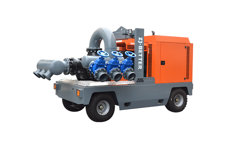
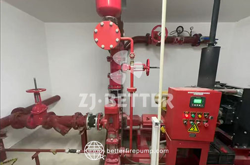
750 GPM @ 120 PSI Fire Pump System On-Site Installation
Sep 09, 2025
Share:
Installing a 750 GPM @ 120 PSI Fire Pump System On-Site: A Comprehensive Guide
Introduction
Installing a 750 GPM fire pump system at 120 psi on-site requires careful planning, precise execution, and strict adherence to NFPA and manufacturer standards. Whether it’s a new installation for a commercial building or replacement of an aging unit, this guide is crafted for fire-safety professionals, engineers, and installers to ensure a reliable, safe, and code-compliant outcome.
I. Pre-Installation Planning
-
Site Assessment & Design Review
Begin with a detailed review of the project site, hydraulic calculations, and the mechanical room layout. Confirm that building utilities can support a 750 GPM fire pump operating at 120 psi, and validate space, foundation, and clearances per NFPA 20 (Installation of Stationary Pumps for Fire Protection). -
Foundation & Mounting
A robust, level concrete foundation is essential. Isolate vibrations using flexible hoses or vibration dampeners. Anchor the pump per manufacturer torque specification to maintain alignment under operating loads. -
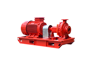
Equipment Inspection
On delivery, inspect all components—the pump, diesel or electric driver, controllers, suction and discharge piping—for damage or missing parts. Check nameplates and performance curves to verify the 750 GPM @ 120 psi ratings. -
Permits & Compliance
Secure all necessary permits. Ensure installations meet local fire codes, NFPA 20, NFPA 25 (Pump Maintenance), NFPA 70 (Electrical), and any jurisdictional requirements.
.jpg)
II. Mechanical Installation
-
Positioning the Pump
Mount the pump driver (motor or diesel engine) so that service access is clear. Ensure clearance around coupling and driver for maintenance. -
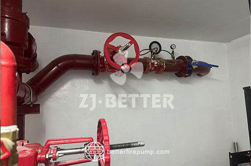
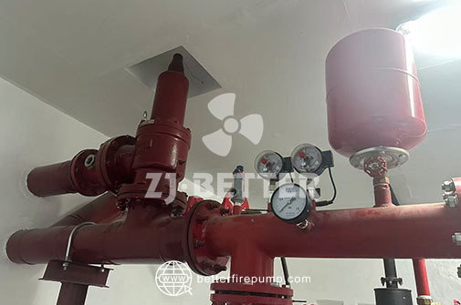
Suction & Discharge Piping
Use rigidly supported piping to avoid misalignment. Suction piping must be short, straight, with smooth transitions, minimal elbows, and a full-sized check valve upstream of the pump. On the discharge side, install pressure-rated piping, control valves, and a non-return check valve. Pipe sizing must handle 750 GPM with minimal friction losses, preserving the 120 psi outlet pressure. -
Flexible Connections
Install flexible hoses close to the pump on suction and discharge lines to absorb misalignment and vibration, protecting both piping and pump. -
Coupling Alignment
After mounting, ensure perfect alignment between pump and driver shafts using dial indicators or laser alignment tools. Even minor misalignment can reduce bearing life and performance. -
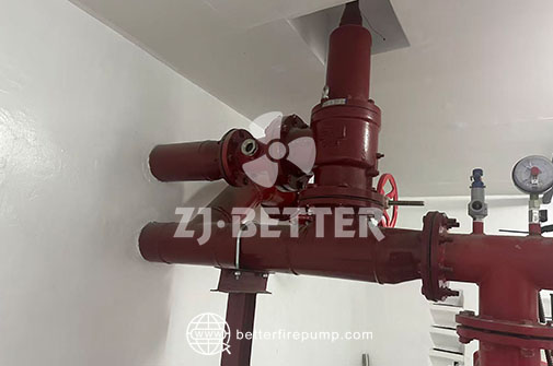
Accessory Installations
Fit a throttle valve (if motor-driven) or bypass (if diesel). Install pressure gauges, relief valves, and local alarm pressure ports. Confirm all RPZ or backflow prevention devices align with fire-sprinkler system specifications.
III. Electrical and Control Work
-
Power Supply & Wiring
Confirm electrical service matches motor nameplate voltage and phase, and that power cabling is sized per NEC and motor FLA ratings. Grounding must comply with NEC, with dedicated ground rods if required by jurisdiction. -
Control Panel Setup
Mount fire pump control panel in a dedicated accessible space. Connect sensors (pressure, flow, temperature) and safety interlocks. Ensure emergency stop and status indicators are positioned optimally. -
Automatic Starting & Monitoring
For electric systems, configure automatic start on water-flow demand. For diesel setups, establish automatic load start and engine pre-warm circuits. Integrate remote signals to central alarm systems or building management.
IV. Commissioning & Testing
-
Initial Checks
Purge air from suction lines, fill the pump casing, and check for leaks. Manually rotate the pump shaft (coupler disconnected) for smooth motion. -
No-Load Run (Jog Test)
Energize the motor or start the diesel engine briefly. Monitor for vibration, noise, abnormal temperature, and check pressure gauge response. -
Performance Test
Simulate fire-demand conditions by opening a testing header or calibrator, drawing 750 GPM. Record pump suction and discharge pressures and driver load (amps or fuel consumption) to verify 120 psi discharge at rated flow. -
Safety Device Validation
Test flow switches, pressure alarms, low-oil shutdown (for diesel), and thermal sensors. Ensure all alarms trigger correctly and remote status is communicated per design. -
Documentation & Handover
Complete test reports capturing pressure-flow curves, amperage, fuel usage, and pump performance versus nameplate. Provide maintenance manuals, spare parts lists, and recommended service schedule to the end user.
V. Maintenance & Operational Best Practices
-
Scheduled Exercises
NFPA 25 requires monthly churn and annual full flow tests. Document results, verifying the pump still meets performance criteria and that 120 psi @ 750 GPM is maintained. -
Lubrication & Bearing Checks
Grease bearings as per manufacturer intervals. Track temperature and noise. Re-align couplings when service builds up. -
Storage for Diesel Sets
Operate the diesel periodically—even without demand—to prevent seal drying, verify fuel quality, and maintain battery charge. -
Winterization
If located in a cold climate, provide freeze protection by draining, adding antifreeze, or installing heaters to prevent freezing in suction or discharge lines. -
Refurbishment & Spare Parts
Keep critical spares on-site—mechanical seals, gaskets, pressure sensors—to reduce downtime during servicing.
VI. Common Pitfalls & Troubleshooting
-
Misalignment/Vibrations can damage coupling and bearings. Always realign after installation or maintenance.
-
Air Entrapment in suction lines can cause cavitation—always bleed completely.
-
Inadequate Power Supply leads to motor overcurrent or failure. Verify electrical system capacity.
-
Inconsistent Flow Testing due to improper test headers. Use calibrated equipment and confirm system integrity.
-
Ignoring NFPA Requirements can void warranties or violate code compliance. Always document and schedule testing, and maintain records.
Conclusion
Implementing an on-site 750 GPM fire pump system at 120 psi involves meticulous coordination across mechanical, electrical, and safety domains. From robust foundation work and precise alignment to electrical integration and comprehensive commissioning, each step is vital for performance and reliability. Ongoing maintenance, detailed documentation, and strict adherence to NFPA standards ensure that your installation remains operational and compliant for years to come.
By following this structured guide, fire-safety professionals will be equipped to handle installations confidently, delivering dependable fire-pump performance when it matters most.