.png)
.png)
.png)
How to Design a Reliable Fire Pump Intake System
Dec 04, 2025
Share:
A fire pump can only perform as well as the water supply behind it. No matter how advanced the pump is—UL listed, diesel or electric, horizontal split case or vertical turbine—its performance will be compromised if the intake system is poorly designed. A reliable fire pump intake system ensures stable pressure, consistent flow, and long-term reliability for the whole fire protection system.
This guide explains the essential principles, NFPA-compliant requirements, engineering considerations, common design mistakes, and practical recommendations for designing a reliable fire pump intake system.
Why the Intake System Matters More Than Most People Think
The intake side of a fire pump—also known as the suction side—is responsible for delivering a continuous, obstruction-free water supply at the required pressure. Problems on the intake side directly lead to:
-
Cavitation
-
Overheating
-
Vibration and noise
-
Reduced pump life
-
Inability to meet NFPA 20 flow and pressure requirements
-
Fire pump failure during an emergency
Most fire pump failures in the field are not caused by the pump itself, but by poor suction piping, undersized strainers, improper tank connection, or insufficient NPSH (Net Positive Suction Head). Designing the intake system properly is the first step toward system reliability.
Step 1: Choose the Correct Water Source
Your intake system must start with a dependable water supply. Common water sources include:
-
Ground-level water storage tanks
-
Underground water reservoirs
-
Rivers, lakes, or wells (usually for vertical turbine fire pumps)
-
Municipal water systems (with or without a break tank)
When selecting the water source, consider:
-
Reliability during emergencies
-
Stability of water level
-
Ease of access for maintenance
-
Contamination and debris levels
-
Head pressure available to the pump
NFPA 20 strongly prefers a flooded suction arrangement for horizontal fire pumps. For deep wells or open water sources, vertical turbine fire pumps are recommended because they are designed to lift water efficiently from below ground.
Step 2: Understand NFPA 20 Requirements for Intake Systems
NFPA 20 sets clear standards for suction piping design to ensure stable pump operation. Key requirements include:
1. Suction Piping Must Be Sized for Minimum Friction Loss
NFPA 20 requires that suction piping be sized so that the total friction loss does not exceed 10 feet of head loss at 150% of pump rated flow.
2. The Suction Pipe Must Be at Least as Large as the Pump Suction Flange
This ensures the pump receives the required water flow without acceleration losses.
3. Use Dedicated Suction Piping for the Fire Pump
Combined piping systems are discouraged because they create pressure fluctuations and introduce contamination risk.
4. Maintain Straight Pipe Length Before the Suction Flange
A minimum of 10 pipe diameters of straight run is recommended to ensure uniform flow and avoid turbulence at the pump inlet.
5. Provide Proper Strainers or Screens for Water Tanks
NFPA 20 requires a minimum area equal to at least 4 times the suction pipe area for suction strainers.
Undersized strainers are a common cause of cavitation and performance loss.
Step 3: Select the Correct Pump Type Based on the Intake Conditions
The intake system design is deeply connected to the fire pump you choose:
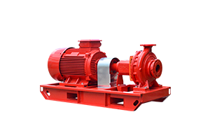
Horizontal Split Case Fire Pump
-
Requires a positive flooded suction
-
Best for stable water supply tanks
-
Sensitive to poor suction conditions
End Suction Fire Pump
-
Also needs a flooded suction
-
Used when space is limited
-
Not suitable for long suction runs
Vertical Turbine Fire Pump
-
Designed for deep wells or suction lift applications
-
Pump bowl assembly sits underwater
-
Eliminates cavitation risk from suction piping
Vertical Inline Fire Pump
-
Compact design but requires excellent suction layout
-
Often used in high-rise buildings with stable tank placement
Choosing the right pump eliminates many future problems and ensures compatibility with the intake system's layout.
Step 4: Design Suction Piping for Maximum Reliability
The suction piping layout determines water stability at the pump inlet.
1. Keep Suction Piping Short and Straight
Long suction pipes create friction loss and turbulence.
Avoid excessive elbows, reducers, or check valves on the suction side.
2. Avoid Air Entrapment at All Costs
Air on the suction side can cause pump failure.
Design considerations:
-
No high points in piping where air can collect
-
Use eccentric reducers installed flat on top
-
Properly vent the tank inlet and piping
3. Maintain Low Flow Velocities
NFPA 20 recommends suction pipe velocities under:
-
15 ft/s for suction piping
Lower velocities reduce friction loss and prevent vortex formation.
4. Use Eccentric Reducers at the Pump Inlet
Reducers should be oriented to avoid air pockets, ensuring smooth flow into the pump.
5. Install Isolation Valves on the Suction Side
Gate valves or butterfly valves are acceptable.
Never use a check valve on the suction side.
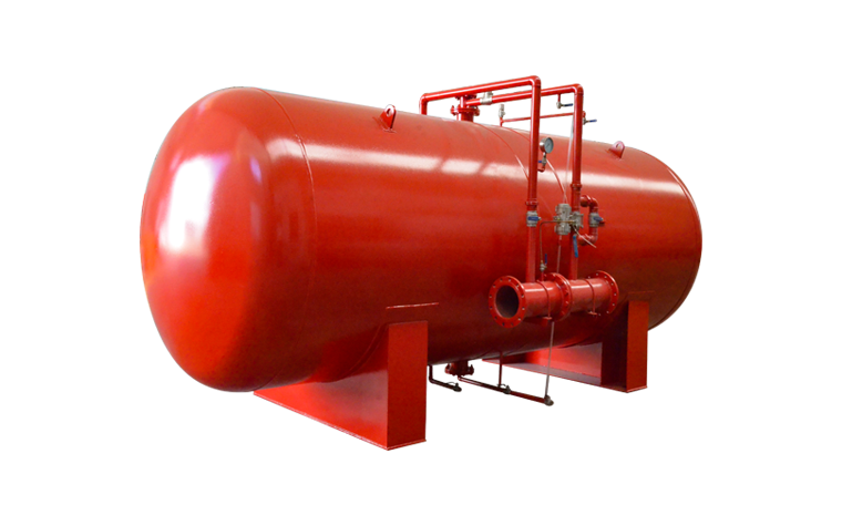
Step 5: Follow Best Practices for Fire Water Tanks
If your fire pump intake system connects to a storage tank, consider these factors:
1. Proper Suction Pipe Submergence
To avoid vortexing, NFPA 20 provides minimum submergence depths based on flow rate.
In general, provide:
-
At least 4× pipe diameter of submergence
2. Anti-Vortex Plates or Baffles
These help stabilize water flow and prevent air ingress.
3. Adequate Tank Outlet Elevation
Tank outlets should be positioned to ensure complete drainage while preventing sediment from entering the suction pipe.
4. Sufficient Strainer Surface Area
Oversized strainers keep flow smooth and reduce the risk of clogging.
5. Clear Access for Maintenance
Technicians should be able to inspect:
-
Strainers
-
Valves
-
Suction elbows
-
Screens and baffles
Water tanks often become contaminated over time, so designing for easy inspection is essential.
Step 6: Consider NPSH (Net Positive Suction Head) Requirements
NPSH is a critical factor in preventing cavitation.
To maintain reliable pump performance:
-
Ensure available NPSH is greater than required NPSH
-
For horizontal pumps, keep the pump below the water level
-
Minimize elevation differences between tank and pump
-
Avoid long, narrow, or complex suction piping
Cavitation occurs when the pressure at the pump inlet drops below the vapor pressure of water. This can severely damage the pump impeller.
Designing for adequate NPSH is one of the most important steps in building a reliable intake system.
Step 7: Special Design Considerations for Vertical Turbine Fire Pumps
Vertical turbine fire pumps operate with the pump bowl assembly submerged in the water source, eliminating suction problems.
Important design notes:
-
Ensure adequate well depth
-
Maintain proper water levels during drought seasons
-
Use screens to prevent debris entering the pump bowls
-
Ensure the discharge head is aligned properly
-
Provide a straight discharge riser for stable flow
Vertical turbines are the best choice for installations where water sources are below ground or where suction lift exists.
Step 8: Avoid the Most Common Intake System Design Mistakes
Many intake system failures happen because of avoidable design errors. Here are the most common mistakes and how to prevent them:
1. Undersized Suction Piping
Always size larger, not smaller.
2. Strainers That Are Too Small
The strainer area must be at least 4× the pipe area.
3. Improper Use of Flex Connectors
Flexible connectors can collapse on the suction side.
4. High Points in Suction Piping
These trap air and cause flow instability.
5. Using Suction Lift for Horizontal Pumps
This leads to priming failures and cavitation.
6. Excessive Elbows Before the Pump Inlet
Too many fittings create turbulence.
7. Locating the Pump Too Far From the Tank
Distance increases friction loss and reduces reliability.
Avoiding these issues ensures stable suction conditions and long-term safety.
Step 9: Perform Hydraulic Calculations and Verify Performance
Before finalizing the intake system, perform hydraulic calculations to verify:
-
Friction loss at 150% rated flow
-
NPSH available
-
Velocity in pipes
-
Tank water circulation
-
Head loss across strainers
These calculations help confirm that the layout meets NFPA 20 requirements and will deliver reliable performance during operation and testing.

Step 10: Implement Reliable Testing and Maintenance Procedures
Even the best-designed intake system requires regular testing and maintenance. Recommended practices include:
-
Weekly fire pump churn tests
-
Monthly tank level checks
-
Quarterly strainer cleaning
-
Annual full flow pump test
-
Regular inspection of valves, reducers, elbows, and piping
Maintenance ensures that the intake system remains reliable years after installation.
Conclusion
A reliable fire pump intake system is essential for ensuring consistent water supply, preventing cavitation, and maintaining stable pump operation during a fire emergency. By following NFPA 20 guidelines, selecting appropriate sizing, designing efficient suction piping, and avoiding common errors, designers and installers can ensure that their fire pump performs exactly as required—when it matters most.