
.png)
.png)
.png)
How to Test a Fire Pump After Installation
Sep 18, 2026
Share:
Installing a fire pump is only the beginning of creating a reliable fire protection system. After installation, the pump, driver, controller, piping, valves, and related equipment must be tested to confirm that the complete system operates as intended.
A properly conducted fire pump test can identify installation problems before the system is placed into service. It can also verify that the pump can deliver the required flow and pressure under operating conditions. For building owners, fire protection contractors, engineers, and facility managers, post-installation testing is an essential part of commissioning a fire pump system.
The exact testing procedure depends on the pump type, driver, system design, applicable regulations, and project requirements. For UL listed or other certified fire pump equipment, the manufacturer's instructions and applicable certification requirements should also be followed.
This guide explains the key steps involved in testing a fire pump after installation and highlights common issues that should be checked before the system is accepted for operation.
.jpg)
1. Review the Installation Before Starting the Test
Before starting the fire pump, conduct a complete visual and mechanical inspection. Testing should not begin until the installation has been checked for obvious problems.
Confirm that the fire pump is installed according to the approved drawings and manufacturer's requirements. Check the pump foundation, mounting, alignment, coupling, suction piping, discharge piping, valves, gauges, controller, and driver.
All major valves should be in their correct operating positions. Suction and discharge piping should be properly supported, and there should be no visible leakage from flanges, fittings, seals, or connections.
For horizontal split-case, end-suction, vertical turbine, and other pump configurations, installation requirements can vary significantly. The inspection should therefore be based on the specific pump design rather than a generic checklist.
The pump room should also provide suitable access, ventilation, lighting, drainage, and operating conditions. For diesel-driven fire pumps, fuel supply, exhaust, cooling, ventilation, and battery systems require particular attention.
2. Check the Suction Supply
A reliable water supply is fundamental to fire pump performance.
Before running the pump, verify that the suction tank, water source, or supply connection contains sufficient water. Check the suction valve and ensure that the suction line is properly filled and free from conditions that could restrict water flow.
Inspect the suction pressure gauge and confirm that it is correctly installed and functional. If the pump uses a suction tank, check the tank level and associated valves. For a vertical turbine fire pump, the water level and suction conditions should be carefully checked because the pump depends on the available water depth and installation arrangement.
Any unusual restriction, air pocket, improperly positioned valve, or inadequate suction supply can affect pump performance and may lead to unstable operation or cavitation.
3. Inspect the Pump and Driver
The pump and driver should be inspected individually before the system is operated.
For an electric motor-driven fire pump, check the electrical connections, voltage, phase sequence, grounding, motor condition, controller settings, and starting equipment. The motor should rotate in the correct direction.
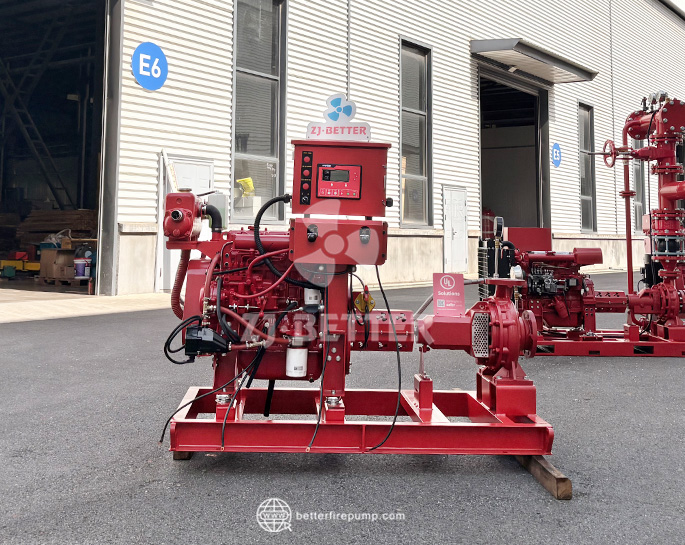
For a diesel engine-driven fire pump, inspect the fuel system, engine oil, coolant, batteries, battery connections, exhaust system, ventilation, and starting system. Confirm that the fuel tank contains an adequate amount of fuel for the test.
The pump coupling should be properly aligned and guarded. Bearings and other components should be checked according to the manufacturer's instructions.
If the pump has been stored for an extended period before installation, additional inspection may be necessary before commissioning.
4. Verify the Jockey Pump and Pressure Settings
Many fire protection systems include a jockey pump to maintain system pressure and compensate for small pressure losses.
Before testing the main fire pump, verify that the jockey pump operates correctly. Check its starting and stopping pressure settings and confirm that it maintains the required system pressure without unnecessarily starting the main fire pump.
The main fire pump and jockey pump should have appropriate pressure settings so that the jockey pump handles normal minor pressure losses while the main fire pump starts when there is a genuine demand for fire protection water.
Incorrect pressure settings can cause frequent main pump starts, unstable system pressure, or unnecessary mechanical and electrical stress.
5. Perform a No-Flow or Churn Test
The first operating test is generally performed with the pump running and without opening the system to full flow.
This is commonly referred to as a churn or no-flow test. During this test, observe the pump discharge pressure, suction pressure, driver operation, vibration, noise, and overall condition.
The pump should start smoothly and operate without abnormal noise or excessive vibration. Check the mechanical seal or packing area for leakage and inspect the pump casing, piping, valves, and connections.
For an electric fire pump, monitor the motor and controller during startup. For a diesel fire pump, observe engine speed, oil pressure, coolant temperature, battery condition, exhaust, and other operating parameters.
The pressure recorded during the no-flow test should be compared with the manufacturer's performance information and the approved project requirements.
6. Conduct the Flow Test
A fire pump should not be evaluated only at no-flow conditions. A flow test is necessary to determine whether the pump can provide the required capacity and pressure.
During the flow test, water is discharged through an approved test arrangement. Flow should be increased through several test points so that the pump performance can be evaluated across its operating range.
Typical test points may include:
- No-flow or churn condition
- Intermediate flow
- Rated flow
- Higher flow condition required by the applicable test procedure
At each test point, record the pump flow rate, suction pressure, and discharge pressure. For electric motor-driven pumps, record relevant electrical parameters. For diesel-driven pumps, record the engine operating parameters required by the test procedure.
The measured results should then be compared with the pump's certified or specified performance curve and the requirements established for the project.
7. Measure Flow Accurately
Accurate flow measurement is one of the most important parts of a fire pump performance test.
Depending on the installation, flow may be measured using a calibrated flow meter, test header, calibrated test equipment, or another approved method.
The measurement equipment should be suitable for the expected flow range and installed correctly. Incorrect flow measurement can make an otherwise reliable pump appear to underperform or overperform.
Record the flow and pressure at each test point. Maintaining a detailed test record is important because these results can become a baseline for future inspections and maintenance.
For example, if a pump delivers significantly different performance during a future annual test, the historical commissioning data can help identify whether the pump, water supply, piping, or other component has changed.
8. Check Pump Pressure and Performance
The primary purpose of the performance test is to confirm that the pump can deliver the required pressure at the required flow.
Compare the measured performance against the pump's approved performance information. The evaluation should consider the complete test setup, including suction conditions, discharge arrangement, measurement accuracy, and applicable acceptance criteria.
A pump that produces the correct pressure at no flow does not necessarily mean that it will perform correctly at rated flow.
For this reason, both pressure and flow must be evaluated together.
If the measured results do not meet the expected performance, do not immediately assume that the pump itself is defective. Possible causes can include inadequate water supply, incorrect valve positions, blocked strainers, incorrect rotation, air in the suction system, inaccurate test equipment, excessive piping losses, or installation problems.
9. Check for Cavitation, Vibration, and Abnormal Noise
During the test, pay close attention to the physical behavior of the pump.
Unusual vibration, rattling, knocking, or unstable pressure can indicate a problem with the installation or operating conditions.
Cavitation is particularly important because it can damage pump components and reduce performance. It may be associated with inadequate suction pressure, excessive suction losses, high water temperature, blocked suction piping, or other unfavorable operating conditions.
Check the pump, motor or engine, coupling, bearings, piping, and valves throughout the test.
A stable pump should operate without abnormal vibration or noise. Any unusual condition should be investigated before the fire pump is placed into normal service.
10. Test the Automatic Start Function
After confirming that the pump can operate manually, verify that the automatic starting function works correctly.
A fire pump controller should be able to respond to the required pressure drop or other initiating condition. The pump should start automatically when the system reaches the appropriate starting pressure.
After starting, verify that the pump continues operating as required by the applicable system design and testing procedure.
The automatic start test is particularly important because a fire pump may sit idle for long periods and only be required to operate during an emergency.
The test should also confirm that the jockey pump and main fire pump interact correctly without causing unintended cycling.
11. Test the Controller and Alarms
The fire pump controller is a critical part of the overall system.
Check manual and automatic starting functions, status indicators, alarms, monitoring signals, and other required controller functions.
For diesel fire pump systems, verify the relevant engine alarms and indications, such as low oil pressure, high coolant temperature, overspeed, battery problems, and other applicable conditions.
For electric fire pumps, check power availability, phase-related indications, controller status, and other required electrical monitoring functions.
The exact alarm and monitoring requirements depend on the equipment and applicable standards, so the manufacturer's documentation and project specifications should be followed.
12. Check Diesel Engine Operation
Diesel-driven fire pumps require additional attention during testing.
Before and during operation, monitor engine speed, oil pressure, coolant temperature, fuel level, battery voltage, exhaust conditions, and other applicable parameters.
The engine should reach and maintain the required operating speed without abnormal fluctuations.
Check the exhaust system for proper operation and ensure that the pump room has adequate ventilation. Diesel engines generate heat and exhaust gases, so insufficient ventilation can affect both engine performance and room conditions.
After the test, inspect the engine and associated systems for leaks or abnormal conditions.
13. Check Electric Motor Operation
For electric fire pumps, electrical performance should be checked throughout the test.
Record relevant voltage and current values according to the applicable test procedure. Observe the motor during starting and operation and check for abnormal heating, noise, vibration, or electrical indications.
The available power supply should be capable of supporting the fire pump under the required operating conditions.
If abnormal current or unstable operation is observed, investigate the electrical supply, motor, controller, connections, and pump operating conditions before completing commissioning.
14. Record and Document the Test Results
A fire pump test should always produce a clear record.
Document the pump identification, date of test, test personnel, water supply conditions, suction pressure, discharge pressure, flow rate, driver information, controller status, and relevant observations.
For each test point, record the measured values accurately.
It is also useful to retain the commissioning results as a baseline for future maintenance. Comparing future test results with the original installation test can help identify gradual changes in pump performance.
A complete record also provides useful information for building owners, facility managers, fire protection contractors, inspectors, and maintenance teams.
15. Resolve Problems Before Final Acceptance
If the fire pump does not meet the expected performance during testing, the issue should be investigated before the system is accepted.
Common problems include incorrect motor rotation, insufficient suction supply, improperly positioned valves, blocked piping, air entering the suction system, incorrect pressure settings, inadequate electrical supply, diesel engine problems, and inaccurate flow measurement.
Do not simply adjust the test results or accept abnormal readings without identifying the cause.
The objective of commissioning is not merely to demonstrate that the pump can run. The objective is to verify that the complete fire pump system can provide the required fire protection performance when it is needed.
Final Checklist for Fire Pump Testing
Before completing the commissioning process, confirm that:
The pump and driver are correctly installed.
The suction water supply is adequate.
Suction and discharge valves are correctly positioned.
The pump starts manually and automatically.
The jockey pump operates correctly.
The pump passes the no-flow test.
The pump passes the required flow tests.
Flow and pressure measurements are accurately recorded.
The driver operates within the required parameters.
There is no abnormal vibration, noise, leakage, or cavitation.
The controller and required alarms operate correctly.
The test results meet the applicable project and equipment requirements.
All test documentation has been completed and retained.
Conclusion
Testing a fire pump after installation is an essential step in commissioning a reliable fire protection system. A complete test should go beyond simply starting the pump. It should verify the water supply, pump performance, driver operation, controller functions, automatic starting, pressure, flow, and overall system condition.
Careful commissioning can identify installation problems before they become failures during an emergency. It also establishes valuable baseline performance data for future inspections, maintenance, and troubleshooting.
For fire pump manufacturers, contractors, engineers, and building owners, proper testing is an important part of ensuring that the fire protection system is ready to perform when required. By following the appropriate testing procedure and documenting the results carefully, stakeholders can have greater confidence in the reliability and performance of the installed fire pump system.