.png)
.png)
.png)
How to Verify Fire Pump Performance?
Jun 11, 2026
Share:
Fire pumps are among the most critical components in any fire protection system. Their purpose is straightforward: deliver sufficient water flow and pressure when a fire emergency occurs. However, simply installing a fire pump does not guarantee reliable operation. Performance verification is essential to confirm that the pump operates according to design requirements and delivers expected results under real operating conditions.
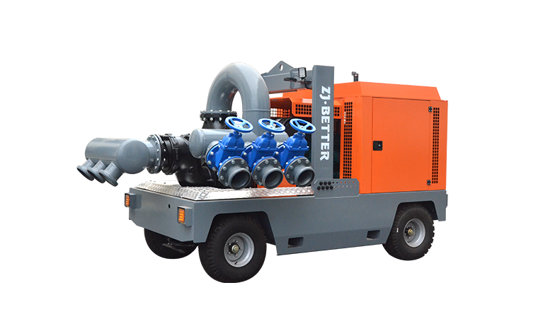
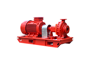
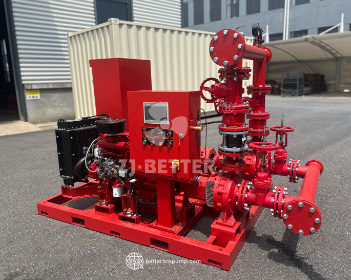
Whether the system uses an electric fire pump, diesel engine fire pump, split case fire pump, vertical turbine fire pump, or a complete fire pump package, performance testing ensures the equipment performs safely, efficiently, and in accordance with applicable standards.
This guide explains how to verify fire pump performance, the testing methods commonly used in the industry, key measurements to evaluate, and practical recommendations to maintain long-term reliability.
.jpg)
Why Fire Pump Performance Verification Matters
A fire pump exists for one reason: to supply water when the normal water source cannot provide adequate pressure or flow.
Without performance verification, potential problems may remain hidden, including:
- Incorrect pump selection
- Installation defects
- Mechanical misalignment
- Air leakage in suction lines
- Improper driver speed
- Control panel issues
- Flow restrictions
- Pressure losses
- System inefficiencies
Performance testing helps confirm:
- Design flow requirements are achieved
- Rated pressure is maintained
- Equipment complies with project specifications
- System reliability during emergency operation
- Long-term operational readiness
Verification should not only occur during commissioning but continue throughout the service life of the system.
Understand Fire Pump Rated Performance
Before performing any verification, understand the fire pump’s rated operating conditions.
Typical specifications include:
- Rated Flow (GPM or L/min)
- Rated Pressure (PSI, Bar, kPa)
- Rated Speed (RPM)
- Driver Power (kW or HP)
- Suction Pressure
- Discharge Pressure
Manufacturers establish performance curves during factory testing. These curves illustrate the relationship between flow rate and pressure.
A properly operating fire pump generally demonstrates:
- 100% rated flow at rated pressure
- Stable operation without vibration
- Acceptable efficiency levels
- Adequate performance at churn conditions
- Sufficient capacity at overload conditions
The pump should operate within the approved performance envelope.
Step 1: Prepare for Fire Pump Testing
Preparation directly affects testing accuracy.
Review Project Documentation
Collect and verify:
- Pump datasheets
- Approved shop drawings
- Hydraulic calculations
- Manufacturer performance curves
- Commissioning procedures
- Applicable standards
Confirm that installed equipment matches approved specifications.
Inspect Mechanical Installation
Check:
- Pump alignment
- Pipe supports
- Valve positions
- Flexible coupling condition
- Fuel supply for diesel systems
- Electrical connections
- Instrument calibration
Testing with unresolved installation issues can lead to inaccurate results.
Verify Instrument Accuracy
Performance verification depends on measurement precision.
Common instruments include:
- Pressure gauges
- Flow meters
- Tachometers
- Temperature sensors
- Vibration meters
- Data loggers
Calibrate instruments before testing.
Step 2: Conduct Visual and Operational Inspection
Before introducing full flow conditions, perform a startup inspection.
Observe:
- Pump startup sequence
- Controller operation
- Driver stability
- Lubrication condition
- Cooling system performance
- Abnormal noise
- Leakage points
For diesel fire pumps, verify:
- Battery voltage
- Engine temperature
- Fuel pressure
- Exhaust condition
For electric fire pumps, verify:
- Voltage balance
- Current draw
- Motor temperature
- Phase consistency
Operational abnormalities should be corrected before proceeding.
Step 3: Perform Churn Test (No-Flow Test)
The churn test evaluates pump behavior with discharge flow closed.
Objectives:
- Verify maximum pressure
- Confirm stable operation
- Check vibration levels
- Monitor temperature rise
Testing procedure:
- Start the fire pump.
- Keep discharge closed.
- Record suction pressure.
- Record discharge pressure.
- Monitor operating conditions.
Typical evaluation points:
- Stable pressure
- No excessive overheating
- Minimal vibration
- Proper controller response
Although churn conditions do not represent actual firefighting demand, they provide important baseline data.
Step 4: Measure Performance at Rated Flow
The rated flow test confirms whether the pump achieves designed operating conditions.
Testing process:
- Open test header gradually.
- Increase flow toward rated capacity.
- Stabilize operation.
- Measure pressure and flow.
Record:
- Flow rate
- Suction pressure
- Discharge pressure
- Speed
- Driver load
- Temperature
Compare measured values against manufacturer curves.
Key questions:
- Is rated flow achieved?
- Is discharge pressure within tolerance?
- Is pump speed stable?
Failure to meet design values may indicate system restrictions or pump deficiencies.
Step 5: Conduct Peak Demand Performance Verification
Fire pumps should maintain operation beyond rated conditions.
A common practice includes testing at elevated flow levels to evaluate reserve capacity.
Monitor:
- Pressure drop behavior
- Driver overload
- Cavitation symptoms
- Mechanical vibration
- Temperature increase
Signs of poor performance include:
- Pressure collapse
- Excessive noise
- Flow instability
- Driver overheating
- Loss of suction
Performance margins help determine system resilience during severe fire conditions.
Step 6: Compare Results with Fire Pump Performance Curves
Performance curves are the most valuable verification tool.
A typical curve shows:
- Flow vs pressure
- Efficiency
- Power demand
- Operating range
Plot measured results against factory test curves.
Interpretation examples:
Curve Matches Design
Indicates:
- Correct installation
- Normal operation
- Acceptable hydraulic performance
Lower Pressure Than Expected
Possible causes:
- Suction restrictions
- Air entrainment
- Incorrect rotation
- Excessive friction loss
Higher Power Consumption
Possible causes:
- Misalignment
- Mechanical drag
- Pump wear
- Improper speed
Trend analysis over time reveals gradual degradation.
Step 7: Verify Driver Performance
Pump verification is incomplete without evaluating the driver.
Electric Motor Verification
Measure:
- Voltage
- Current
- Frequency
- Power factor
- Motor temperature
Common issues:
- Undervoltage
- Excess current
- Bearing wear
Diesel Engine Verification
Measure:
- RPM
- Fuel consumption
- Exhaust temperature
- Cooling effectiveness
Common issues:
- Fuel delivery limitations
- Governor instability
- Cooling deficiencies
Driver performance directly affects hydraulic output.
Step 8: Evaluate Pressure Stability and System Response
Pressure consistency is often overlooked.
Observe:
- Start pressure
- Running pressure
- Pressure fluctuations
- Controller transitions
Pressure instability may indicate:
- Air pockets
- Control issues
- Pipe vibration
- Valve problems
A stable pressure profile supports reliable emergency performance.
Step 9: Document and Analyze Test Results
Proper documentation creates traceability.
Include:
- Test date
- Environmental conditions
- Equipment identification
- Calibration records
- Pressure readings
- Flow measurements
- Observations
- Corrective actions
Create a standard verification report containing:
General Information
- Pump model
- Driver type
- Installation location
Measured Data
- Flow
- Pressure
- RPM
- Temperature
Conclusions
- Pass or fail status
- Recommendations
Historical records support predictive maintenance.
Common Reasons Fire Pumps Fail Performance Verification
Even high-quality equipment can experience issues.
Frequent causes include:
Insufficient Water Supply
Restricted suction conditions reduce performance.
Incorrect Pipe Installation
Poor layout creates hydraulic losses.
Air Entrapment
Air lowers effective pump capacity.
Driver Speed Problems
Speed deviations change pressure and flow.
Mechanical Wear
Impeller and bearing wear reduce efficiency.
Instrument Errors
Faulty measurements lead to incorrect conclusions.
Root cause investigation should follow any failed test.
Best Practices for Long-Term Fire Pump Reliability
Verification should become a continuous process.
Recommended practices:
- Perform routine inspection schedules
- Conduct annual performance testing
- Maintain calibrated instruments
- Record trend data
- Train maintenance personnel
- Review controller logs
- Test under realistic operating conditions
For critical facilities, consider implementing digital monitoring and predictive maintenance strategies.
Final Thoughts
Verifying fire pump performance is more than a commissioning requirement—it is a practical process that confirms whether a fire protection system will perform when needed most.
Effective verification combines inspection, flow testing, pressure analysis, driver evaluation, and comparison against performance curves. Regular testing helps identify hidden issues early, extends equipment life, and improves confidence in emergency response capability.
Next: